Need help understanding how VLANs, Ports, Interfaces, and Adapters work together

Hi,

It looks like I’ll have to dive into this topic bit deeper, as just enabling the “Guest Network” in Foris did not work as expected: The Computer connected to “Port 4” (next to the WAN port) is still assigned an IP from the “normal” network. And it can connect to all local computers as well as to the internet.

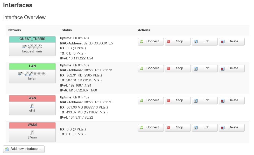
I expected that Computer to have an IP from the range specified in the guest network settings and be able to connect only to the internet and not even seeing my local computers. Normal network is 192.168.1.1/255.255.255.0 while guest network is 10.111.222.1/255.255.255.0.

Then, I switched to Luci. I think I understand it partially, but some of the options confuse me a lot.

Let’s start with the things I think I understand. Please correct me if I got something wrong.

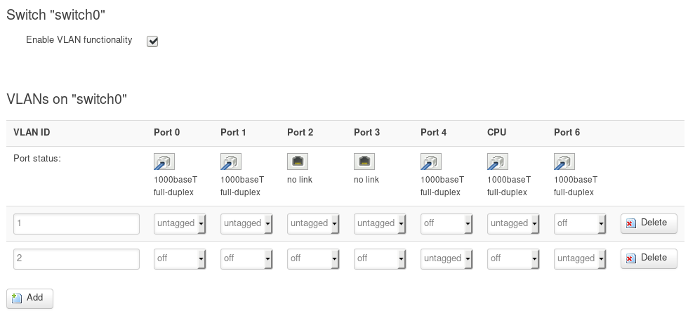
OK, I understand that separation of the networks is done via VLANs, and therefore I need at least 2 of them: one for my “normal” network (VLAN ID 1) and another one for my guest network (VLAN ID 2). These VLANs were set up by Foris and I did not touch these settings so far. The Ports (except CPU) seem to correspond to the physical connectors on the rear side of the box, and Port 6 looks like it’s the WAN port.

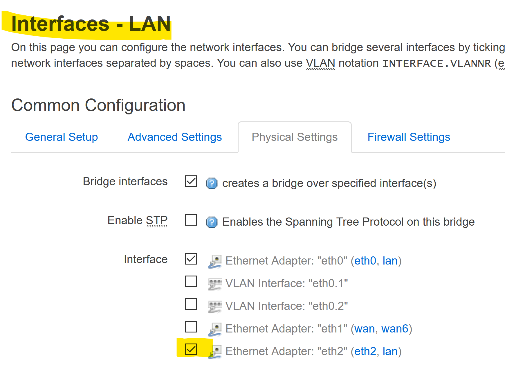
Also appears clear to me … One Interface for every network section.

The things confusing me start here (also did not touch these settings):

I see a mix of Adapters, Interfaces, and Networks. And the names correspond only partially to stuff configured elsewhere.
E.g. the VLAN Interfaces … is eth0.1 VLAN ID 1 ?
Where do the Ethernet Adapters eth1 and eth2 come from ?
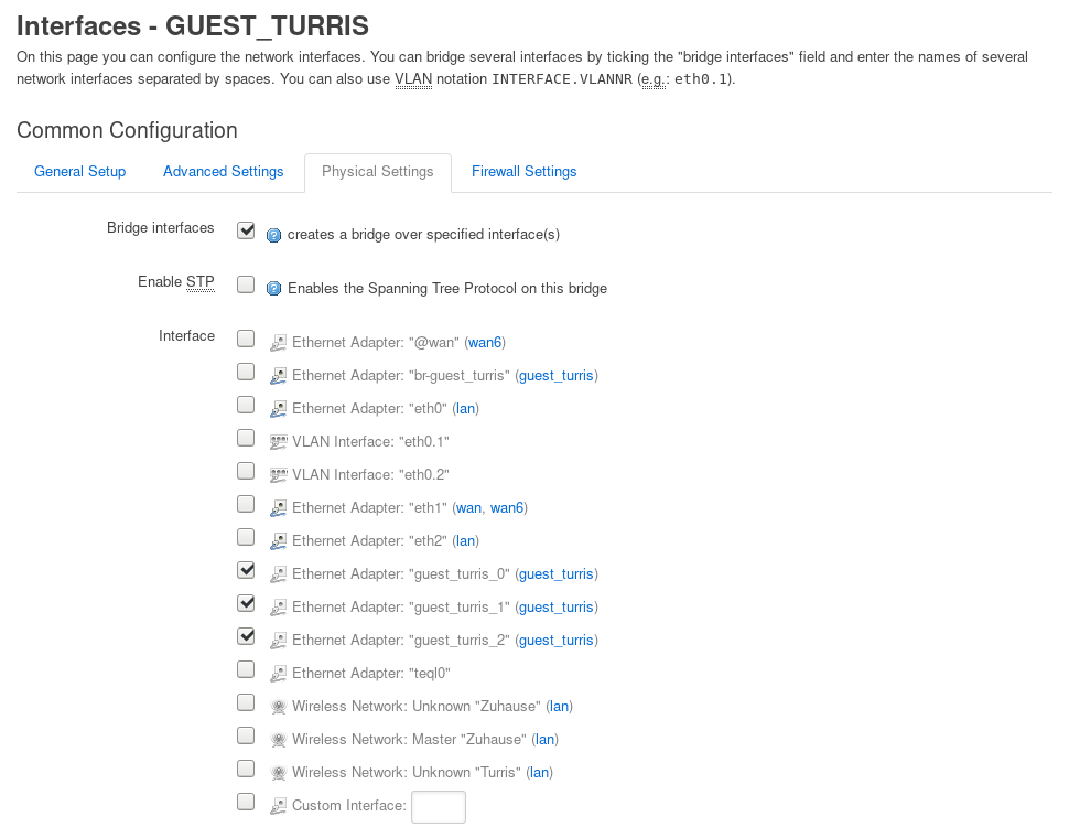
Why are there multiple Adapters with guest_turris in the name (br-guest_turris, guest_turris_0, guest_turris_1, guest_turris_2) ?
Are there different types of Ethernet Adapters (at least, there are different icons, but they could as well be status icons) ?

And finally: What’s wrong with my settings ? Why does the Computer that’s connected to (physical) Port 4 and configured as DHCP client get an IP of the “normal” network instead of the guest network ?

Thanks and Regards,
Markus

Did you already have a look at https://doc.turris.cz/doc/en/howto/vlan_settings_omnia ?

Oops, seems like I overlooked that.

OK, it explains where eth0, eth1, eth2 come from. And it looks I was wrong about Port 6 … it looks like it’s the second CPU connection.

But as far as I understand the wiki article, my switch settings should be correct. Port 4 is connected to eth2 and this way, the two VLANs should be work separately. But they don’t.

I’ve just tried changing the “Physical Settings” of Interface GUEST_TURRIS: removed the checks next to Ethernet Adapter: guest_turris_0, _1, _2 and instead checked VLAN Interface: “eth0.2” but no change.
I’ve shut down the computer, then rebooted the Router, then started the computer again.

The VLAN seems correct to me. Changing the physical setting makes sense.

Not sure if the dhcp lease files survives (and thus retaining a previous lease) a reboot or whether it gets wiped and rewritten upon boot. It should be located in “/tmp/dhcp.leases”
That if dnsmasq is used as dhcp server.

After rebooting the router, /tmp/dhcp.leases is empty. And yes, dnsmasq is used as dhcp server.

From that a.m. howto

if an ethernet cable is connected to any connector LAN0 to LAN3, the given data flow can be seen on the interface eth0. The same goes for the interface br-lan, because eth0 are eth2 connected via bridge - see block config interface ‘lan’ .

It is rather curious to separate eth0 from eth2 via VLAN and then just to join them again in a bridge.
Not sure though whether that would explain the wrong subnet for guest but maybe worth a try to remover eth2 from the lan bridge and maintain eth0.2 assigned to guest.

The way to think about it is to view the switch as a completely separate network device.

If you only want a LAN and guest connection, then you can use eth0 for one and eth2 for the other. Anything more than that and you’ll need to set one of the CPU ports as tagged, and reference the VLAN devices in your interfaces (eth0.1, eth0.3, etc). In you case, keep the switch config the way it is, and set the LAN interface to use eth0 and the guest interface to use eth2. Neither one needs to use a VLAN device, since you only have 2 interfaces that touch the switch. Right now, you have your guest iface set as eth0.2, but that’s not going to work because you have the CPU switch ports set as untagged - the VLAN information has already been removed by the time it hits the CPU.

I’m not really sure why the default config is the way it is. It just causes more load on both the CPU sand switch chip when something on port 4 is communicating with something on 0-3 while only benefitting certain corner cases.

1 Like

It wooooooooorks ! :slight_smile:

Your explanations (both of your’s) helped me a lot. Thank you very much.

Interface LAN is now connected to eth0 and the WLAN Interfaces, while GUEST_TURRIS is connected to eth2.
One more thing is kind of interesting: After changing settings as described above, the Ethernet Adapter: guest_turris_0, _1, _2 were gone. Really curious … they were created automatically and deleted automatically.

I have to say I’m kind of surprised that activating the guest network required some manual configuration at all. I thought the Foris UI was there for doing these things in a wizard-like style, and setting up a guest network is not so unusual.

Maybe I’ve expected too much, but maybe this is a topic where Foris needs some enhancement.

2 Likes